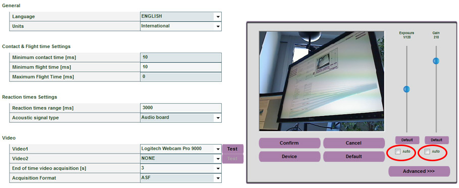
Step 5: From here, stay in ‘utility’ and select the ‘OptoGait HW test’ below basic settings. You should see a diagram of your 2 OptoGait skis with the 96 LED’s. Wait a second or two and then select ‘execute’. If sound is activated, you should hear a ding and then step one foot in between the bars. On the computer screen, the LED’s you’ve interrupted should turn from green to red. (It is not necessary to activate all the LED’s, a few will suffice. If nothing appears to happen, try ‘hardware reset’ just below ‘execute’ and then try again.) Then, select stop in the bottom right corner. You will be asked if you want to filter the LED’s you’ve just interrupted...select ‘no’.
Step 6: After this, select ‘back’ in the bottom right corner, and you are now ready to execute a test. The first thing to do here is create a patient. Along the top left of the screen, select ‘patients’ and then ‘insert/modify patient. Select ‘new patient’ and fill in the appropriate data. In order to acquire the patient’s foot length, have the patient place one foot(only) in between the bars and parallel to them. Click acquire foot length and save the data. Save the patient data and move to the next step.
Step 7: For this example, we will assume you are planning to execute a march in place test. There is no preconfigured test for march in place, so you’ll have to create one of your own. To create your own test, go back to ‘test’ and select ‘define/modify tests’ and then select ‘new test’ on the right. Give your test a name and then select ‘tapping test’ on the test type drag down menu. The start type will be a status change and the start will be inside the area. The starting foot can be the right foot (you can either
a) have the person not march until you click ‘start’ and then begin with their right leg, or
b) have the person already marching and click ‘start’ when the left foot is coming down so that the first full reading will be the right foot going up). The stop type options are simple. An ‘external impulse’ stop demands that the computer user press FnF4 when stop is desired. This gives you the freedom to stop the test at will, rather than the ‘end of time’ stop, which stops the test automatically for you after a specified amount of time. If you select ‘end of time’, a test length parameter will pop out. Enter your time here and you may then save the test.
Step 8: Select ‘test’ along the top, ‘execute’, select your patient and choose the test you’ve just created from the list, and then get your patient into position. Remember that the march in place test must be done perpendicular to the bars. If parallel, no data will acquire. Then, select ‘execute’ and instruct your patient to start marching with the right leg first; or, get the patient marching and select ‘execute’ when the left foot is about to touch down and the right foot to lift. Depending on your stop type, the test will end after the desired amount of time or when you press FnF4.
Step 9: If you want to execute a jump test rather than a march in place, select the preconfigured ‘squat jump 2 legs 5 jumps’ when you are in the ‘test’, ‘execute’ section. Then perform your 5 jumps after you’ve clicked start in the execution page. Save when finished and locate the test in the results section.
Step 10: If you want to execute a gait walk analysis, the first thing to observe is the direction your skis are laid on the treadmill. The towers are known as ‘interface towers.’ If they are in front of the walker, you may execute the preconfigured test called ‘Treadmill Walking 3MPH or 5KM/H’. If the towers are behind the walker, you’ll have to create a test. The easiest way to do this go to ‘test’ along the top and then ‘define/modify test’. Click once on the ‘Treadmill Walking 3MPH or 5KM/H’ test to highlight it, and then select ‘duplicate test’ on the right side. A copy of the test will show up at the bottom of the list with your newly created march in place test. Double click on the newly copied test, and call it ‘Treadmill Gait-Opposite Side’. Then, go down to the last parameter, ‘direction’, and change the direction to opposite side. Now, the test matches the placement of the skis on the treadmill. Save the test and you may execute your gait walk analysis. The execution of the gait analysis begins as such; the user clicks ‘execute’ and video begins acquiring. The test, however, doesn’t begin until you answer the two prompts of Direction (making sure the test matches the direction of the skis) and Treadmill Speed (you aren’t locked into the speed you chose when creating the test so you may run the test multiple times at multiple speeds). After answering the prompts, click ‘start’ and the test begins. Click ‘stop’ when you are satisfied and the test stops. Save it, and you may then analyze the results in the results section.


