


The two-dimensional system
Starting from version 1.7 of the OptoGait software it is possible to use a particular bar configuration for obtaining a two-dimensional measurement area. To the classic bars (which we will call X), more bars (Y) can be added to form a rectangle, where new information can be gathered for the gait tests:
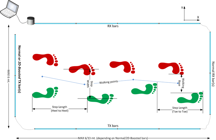
- Step width: distance between the middle support point of each foot
- Walking Base: distance between the innermost foot support points (for superposed steps this value can be negative)
- Walking Points: middle points between the two support feet; their connection defines the gait progress (Line of Progression); conventionally it is expressed in positive values if there is a deviation towards left and negative with a rightward deviation
- Walking Point Gap: progressive variation of the current walking point with respect to the previous one
Hardware
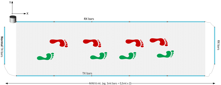
The regular OptoGait bars have a maximum transmission/reception distance of 6 meters; with this hardware you can use at the most 5 meters of 'X' bars and approx. 50 cm of room with the 'Y' bars.
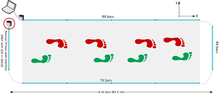
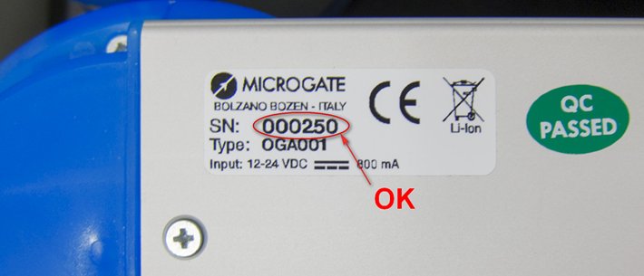
The regular closing Y TX bar is usually a bar WITHOUT interface drum. Updating the firmware of the TX bar with drum (already included with all articles having a serial number higher than 00250) this last hardware type can also be used. Therefore with a 5-meter modular system (Kit £OGA051) it is for example possible to use the complete hardware building a 4-meter-long linear gait system. For serial numbers lower than 00250 it is possible to ship the bar to Microgate or a distributor and receive a free update (shipping costs for sending and receiving are excluded). It is also possible to buy one or more additional single TX bars.
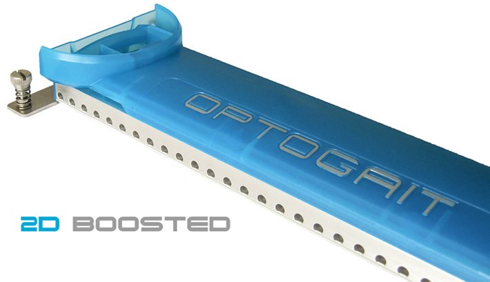
2D Boosted Bar
The maximum length of the 2D course can be increased up to 13 meters purchasing one or more special Y TX bars called '2D-Boosted.' This kind of bar is equipped with stronger transmission LEDs compared to the others and has a front aluminum cover instead of the transparent lenses, in order to direct the narrow infrared LED beam. To help the Y bar alignment at great distances (especially with not perfectly smooth ground), the 2D-Boosted bar is equipped with mechanical trimming devices for applying micrometric elevation and inclination changes.
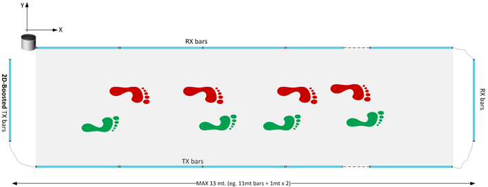
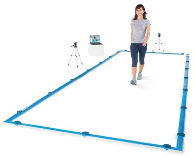
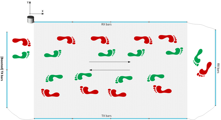
The bars situated on the perpendicular sides are connected using a variable-length cable (usually 1.5/2 m); this allows to distance the actual measurement area (the rectangle formed by the regular bars and highlighted in gray in the following picture) of the Y bars; this area allows the patient to leave the test area without having to jump over the bars or, more frequently, turn around by 180° and go back. In fact, the software allows to carry out an undefined number of back/forth courses recording a sufficient number of steps also in case of linear systems of only a few meters.
For those requiring fixed installations (which are also esthetically appealing), a corner cover is available (without LEDs, only for protection) to cover cables running on the ground (see first picture).
Software
Patient Module
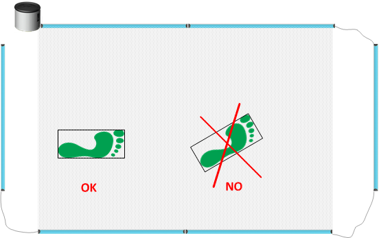
The first result of the 2D configuration on the software is the addition of a new 'Foot Width' field in the Patients' Personal Data. Similarly, this parameter is already present for the foot length and can be measured automatically (and simultaneously) by the system using the <Acquire Foot> function on the patient's card. During acquisition it is advisable to keep the foot as perpendicular as possible to the X and Y bars..
Test Module
Patient Module
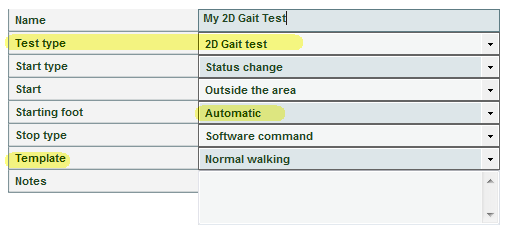
A new test type called '2D Gait Test' has been added (more test and protocol types will be added, such as Tapping, Drift, etc., which will make use of the 2D hardware).
With this new type it is NOT necessary to specify the number of (X and Y) bars connected, as this is detected automatically by the software (the only limitation is that the number of X bars must be >= Y bars).
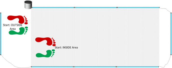
As highlighted, the measurement area is always the area covered by the X bars and not by the whole rectangle; this is very important with respect to the 'Start' parameter; if the athlete starts inside the rectangle, but in any case before the beginning of the X bars, this must be defined as 'OUTSIDE the Area'
The 'Starting Foot' field contains only the Automatic option and therefore it is no longer necessary to define beforehand if the gait begins with the right or left foot, as the Y bars detect it automatically.
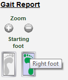
For certain situations it is in any case still possible to change the starting foot during the test phase (Results > View) using previous methods (right click on the grid and 'Change Starting Foot' context menu) or via a new function with two buttons in the Gait Report section. Just press the icon of the required foot to set it as starting foot (the one currently used is colored, whereas the other is grayed out).
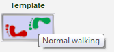
The 'Template' field, which previously contained various gait types besides the normal one (shuffling gait, short steps, short steps tip-tip, etc.) has been considerably simplified; thanks to the greatly improved algorithms for the automatic recognition of  various patterns, it has been possible to reduce the various types to only two, i.e. 'Normal' and 'Overlapping walk.'
Similarly to the foot change, a rapid method has been added for changing the template directly from the Gait Report using the relevant button.
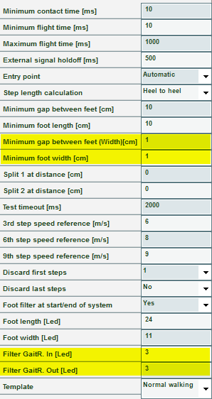
In the Secondary Parameters of the 2D Gait Test there are 4 new parameters, which can already be applied during test definition or during the trial analysis (<Parameters> button).
- Minimum Gap between Feet (width): parameter required by the filter algorithms for specific cases
- Minimum Foot width: similar to the minimum foot length; smaller measures are skipped, because they are considered spurious
- GaitR In and Out Filter: The two parameters expressed in number of sensors (LEDs) indicate the minimum number of sensors interrupted by the gait and triggering the start of the foot contact time (GaitR IN) and the end of the same time (GaitR OUT). See here for a more detailed description
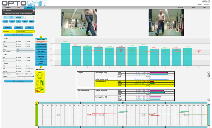
Results Module
In the Results display section, the new features of the 2D hardware are:
- Step Width in the Gait Report
- Step Width, Walking Base, Walking Point, Walking Point Gap columns added to the Gait Data
- In addition to the Gait report, as described above, buttons are available for rapidly changing the 'starting foot' and the 'gait type' template
- The simulation of the footprints and of the interrupted LEDs also shows the status of the Y bars and the line of progression data from the walking points
- A zoom (+ / -) toggle button is featured for increasing the footprint area; the area is furthermore divided by a grid and the indication of the sensor number
- A new search parameter has been added (First Entry and Next Entry) for rapidly finding the first entry in the measurement area or the following entries in case of roundtrip tests.
Optogait Home
More Configurations